
Opis
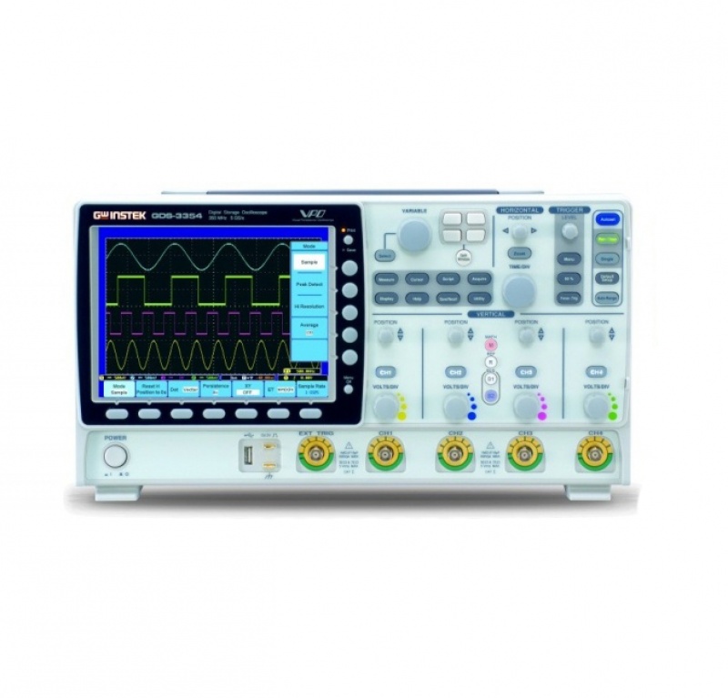
Oscyloskop cyfrowy GDS3504 4x500MHz 4GSa/s, 8 cali
A Hi-tech DSO Platform
The GDS-3000 Series is a new platform of 4-input channels, 500MHz bandwidth, 5GSa/s sampling rate, and VPO waveform display. The split screen feature has been designed to meet the requirements of multi-window & multi-signal tests in the research and the manufacturing fields. The optional power analysis software and the optional serial bus analysis software are available to facilitate the engineer’s tasks in testing and manufacturing of the associated products.
Three new differential probes, GDP-025, GDP-050 & GDP-100, and two new current probes, GCP-005 ,GCP-020 ,GCP-100 and GCP-530 & GCP-1030, are coming along with the GDS-3000 Series to provide total solutions for a wide variety of applications in the industry, service and education market sectors. The GDS-3000 Series, a high-tech platform carrying thoughtful features, brings very high customer value to both general purpose market and professional market.
VPO- Visual Persistence Oscilloscope Signal Processing Technology

UNIQUE SPLIT SCREEN FUNCTION
The unique split screen feature of GDS-3000 Series allows each input channel to be operated independently with respective setting and waveform display. The time base, the vertical sensitivity, and the trigger selections can be done by each channel separately, and the waveform of each input signal can be shown on the individual part of the screen. This nearly four-DSO-in one feature is very useful for the applications that need to simultaneously see the details of multiple waveforms with very different characteristics. The 8-inch high resolution 800×600 LCD display makes the split screen a pleasant observation environment to view the details of complex signals.

COMPLETE SET of TRIGGER FUNCTIONS
Besides Edge trigger, the GDS-3000 Series also offers various trigger functions, including Video, Pulse Width, Runt, Rise Time & Fall Time (specific time length), Alternate, Delay by Time, Delay by Event, and Hold-Off. The high sampling rate, the VPO signal processing & display, and the flexible trigger function all together make the GDS-3000 Series a powerful tool for waveform capture and display of various types of signals.

AUTO RANGE FOR BOTH TIME BASE AND VERTICAL SCALE
The Auto Range function automatically adjusts the time base and/or the vertical scale of displayed waveform when the frequency and/or the amplitude of input signal changed. This function gives user the convenience to have DSO always display waveform in a proper fashion on the screen tracking the frequency and amplitude changes of the input signal. It is especially useful when the user needs to alternately probe and test multiple circuit points containing signals with different frequencies and amplitudes.

DUAL DISPLAY WINDOW ZOOM
The GDS-3000 Series Window Zoom function provides dual display mode to show the main waveform and the magnified section of zoomed-in waveform at the same time. Under „Zoom” mode, the width and the position of zoom-in window over the main waveform can be selected to get the magnified waveform as needed for detailed observation. To quickly and accurately move the zoom-in window to the expected position, the „Coarse” mode helps move the window to the needed position immediately and the „Fine” mode provides fine adjustment to precisely place the window in the exact position.

28 AUTOMATIC MEASUREMENTS
To observe fundamental and harmonic frequency components of a signal, the FFT function on a digital storage oscilloscope is often used. Typically the traditional unit of the FFT is decibel (dB). However, when using dB it is sometimes difficult to identify the fundamental frequency of a signal from a noisy spectrum. With FFTrms function, the GDS-3000 Series can clearly display the fundamental frequency of an acquired waveform.
The FFT function of GDS-3000 supports Rectangular, Hamming, Hanning, and Black-harris windows.

THREE INPUT IMPEDANCE SELECTIONS
Three input impedance, 1M , 75 , and 50 are available for user’s selection. The flexibility of impedance selections, including 1M to get minimum loading effect, 75 to accommodate Video transmission applications and 50 to fit RF communication applications, extends the GDS-3000 Series utilization range.

X-Y MODE


Two high-speed USB 2.0 Host ports located in both front panel and rear panel are used for easy access of stored data. In the rear panel, a USB Device port is available for remote control and hardcopy print-out through a PictBridge compatible printer. RS-232 and LAN interfaces are provided as standard for system communication & ATE applications.
A SVGA video output port allows the transfer of DSO screen image to an external projector or monitor for remote monitoring or big screen observation. A GPIB to USB adaptor is available as an option for interface conversion though the USB Device port in the front panel.

SERIAL BUS ANALYSIS SOFTWARE SUPPORTING I2C, SPI and UART (OPTIONAL)
With serial bus technology being widely used in embedded applications, the proper triggering and analysis of flowing data, control signal and associated pulse waveforms in serial bus communication has been a difficult job and challenge to design engineers. The Serial Bus Analysis software of GDS-3000 Series carries complete analysis tools for triggering and decoding of commonly used serial bus interfaces, including I2C, SPI and UART. Without spending time to study serial bus regulation details, the user only needs to set the trigger condition on GDS-3000 to get the data slots of interest.
Serial Bus Analysis Software
")
")
")
")
")
")