
Kontakt
Znajdź nas:
Twój schowek
(0)
0 szt.(0,00 )
Zaloguj się
Aparatura kontrolno-pomiarowa. 
Dystrybucja, serwis, kalibracja

Kanał otwarty 15 mt.

Dodaj do zapytania

Kod producenta: (HI100)

Opis produktu – Kanał otwarty 15 mt.

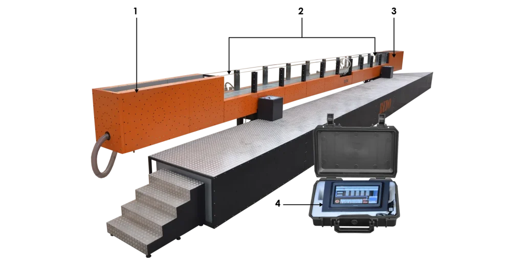
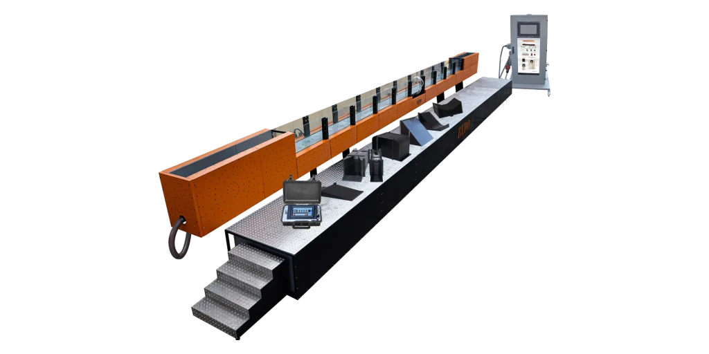
Symulator kanału otwartego (HI100) został zaprojektowany w celu zilustrowania podstaw wymaganych do zrozumienia zmian przepływu w kanale otwartym podczas powodzi i obliczenia zrzutu na zaporach. Trenażer oferuje szeroki zakres eksperymentów, ponieważ jest to zintegrowany system edukacyjny, który składa się z dużego koryta i dużej liczby modułów eksperymentalnych, które można wstawić do koryta w celu wykonania wszystkich rodzajów ćwiczeń i zbadania profili wody wynikających z tych jazów. Trenażer jest dostarczany z oprogramowaniem do sterowania trenażerem i wykonywania pomiarów za pomocą jednostki zdalnego sterowania.


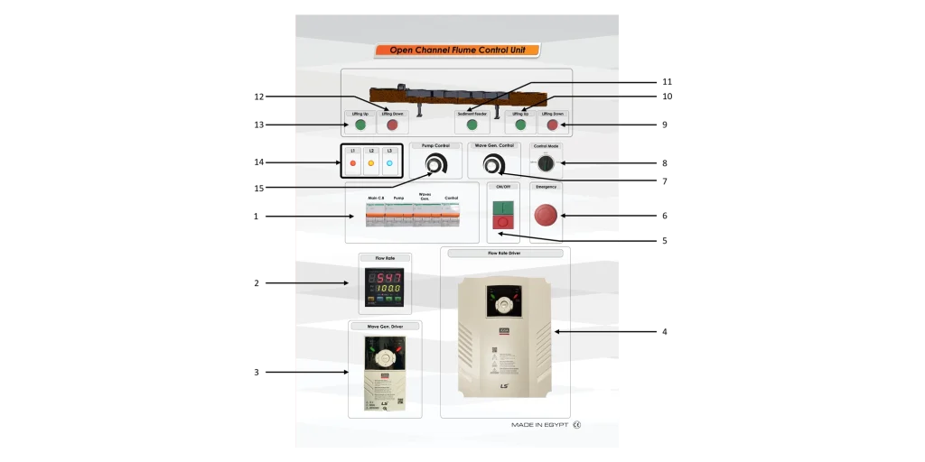
1. Wyłączniki 2. Natężenie przepływu 3. Sterownik generatora fal 4. Sterownik natężenia przepływu 5. Włącznik/wyłącznik sterowania 6. Wyłącznik awaryjny. 7. Sterowanie prędkością generatora fal 8. Tryb sterowania 9. Podnośniki w dół 10. Podnośniki w górę 11. Podajnik osadów 12. Podnośniki w dół 13. Podnośniki w górę 14. Diody LED wskazujące działanie jednostki sterującej 15. Pokrętło regulacji prędkości pompy
Dane techniczne

  • Długość kanału: 15 m.
    • Wymiary kanału W x D: 300 mm x 450 mm
  • Jednostka eksperymentalna
    • Jest podzielona na cztery sekcje po 2. 5 m każda, z sekcją wlotową 2,5 m i sekcją wylotową 2,5 m
  • Pompa
    • Przepływ: 132 m3/godz.
    • Wysokość podnoszenia: 30 m.
    • Zasilanie: 20 KM, z falownikiem o mocy 20 KM.
  • Czujnik przepływu:
    • Czujnik przepływu: łopatkowy.
    • Zakres natężenia przepływu: 0-100 m3/godz.
  • Generator fal:
    • Moc: ¾ KM.
    • Skrzynia biegów: krok w dół od 150 do 110 obr/min.
    • Inwerter: 1 KM.
  • Zbiornik: 1100 L
  • Silnik inklinacyjny
    • moc silnika: 1,1kW
    • prędkość: 935min-1

Zakres dostawy

  • Open Channel Flume 15 mt. (HI100)
  • Twarda instrukcja obsługi

Opcje

  • Struktury sterujące (HI100.01)
    • Brama śluzowa (HI100.01.01)
    • Brama promieniowa (HI100. 01.02)
    • Zestaw jazów płytowych, cztery typy (HI100.01.03)
    • J jaz szerokokrawędziowy (HI100.01.04)
    • Jaz okrężny (HI100.01.05)
    • Jaz syfonowy (HI100. 01.06)
    • Rake (HI100.01.07)
    • Elementy rozpraszania energii (HI100.01.08)
  • Zmiana konstrukcji przekroju (HI100.02)
    • Dno koryta z kamieniami żwirowymi (HI100. 02.01)
    • Parapet (HI100.02.02)
    • Przepust (HI100.02.03)
    • Zestaw filarów, siedem profili (HI100.02.04)
  • Kanały pomiarowe przepływu (HI100. 03)
    • Kopuła Venturiego (HI100.03.01)
    • Kopuła Parshalla (HI100.03.02)
    • Kopuła trapezowa (HI100.03.03)
  • Inne eksperymenty (HI100.04)
    • Wibrujące pale (HI100.04. 01)
    • Generator fal (HI100.04.02)
    • Zestaw plaż (HI100.04.03)
    • Nośnik przyrządów (HI100.04.04)
  • Przyrządy pomiarowe (HI100.05)
    • Poziomomierz (HI100. 05.01)
    • Czujnik przepływu z licznikiem cyfrowym (HI100.05.02)
    • Manometry rurowe (HI100.05.03)
    • Elektroniczny pomiar ciśnienia, 10x 0…50 mbar (HI100.05.04)
  • Oprogramowanie (HI100.06)
  • Zawartość cyfrowa (BI-01)

Szczegóły techniczne

  • Trener jest systemem ilustrującym podstawowe zasady przepływu w kanale otwartym.
  • Trenażer składa się z pięciu głównych jednostek, kanału otwartego, modułów eksperymentalnych, panelu operacyjnego i kontrolnego, jednostki zdalnego sterowania z ekranem dotykowym i jednostki PC.
  • Kanał otwarty, panel operacyjny, panel kontrolny i jednostka PC są połączone ze sobą za pomocą kabli elektrycznych i kabli do gromadzenia danych.
  • Kanał otwarty składa się z sekcji ze wzmocnionego szkła przymocowanych do solidnej konstrukcji z płytą wytrząsającą.
  • Kanał otwarty działa jak zamknięty obieg wody, ponieważ kanał otwarty jest zasilany zbiornikami wody jako zbiornikami zasilającymi i spustowymi oraz pompą o dużej mocy.
  • Kanał otwarty składa się z sekcji wzmocnionych szklanych boków i podstawy ze stali nierdzewnej przymocowanej do solidnej metalowej konstrukcji z płytą wstrząsającą, dwie z sekcji szklanych są stacjami serwisowymi do dostarczania wody o stałym przepływie i odprowadzania wody z powrotem do zbiorników.
  • Zbiorniki wykonane są ze stali nierdzewnej.
  • Każda sekcja podstawy kanału ma cztery czujniki ciśnienia i cztery połączenia manometrów. Każdy czujnik ciśnienia jest połączony z przyłączem manometru. Pary są rozmieszczone w równych odstępach wzdłuż sekcji.
  • Każda sekcja jest również wyposażona w otwory do mocowania modułów eksperymentalnych (jazów).
  • Koryto jest wsparte na prawym i podnoszonym podnośniku, aby pochylić koryto od 0 ° do 2,4 ° za pomocą ich paneli sterowania.
  • Cały trenażer jest sterowany elektrycznie z jednostki operacyjnej i sterującej.
  • Cały trenażer może być sterowany ręcznie za pomocą jednostki operacyjnej i sterującej lub za pomocą oprogramowania za pomocą jednostki zdalnego sterowania.
  • Jednostka operacyjna i sterująca zawiera główne wyłączniki systemu, wyłączniki bezpieczeństwa dla urządzeń elektrycznych zawartych w trenażerze.
  • Oprogramowanie jest zainstalowane w jednostce zdalnego sterowania, aby ułatwić uczestnikom szkolenia poruszanie się po systemie w celu obserwowania strumienia i jednoczesnego sterowania systemem.
  • Jednostka PC demonstruje parametry procesu zarówno w przypadku trybu sterowania ręcznego, jak i trybu sterowania programowego.

Experiments

  • Demonstrating the following:
    • Uniform and non-uniform discharge
    • Flow formulae
    • Flow transition (hydraulic jump)
    • Energy dissipation (hydraulic jump, stilling basin)
    • Flow-measuring flumes
    • Local losses due to obstacles

Optional Accessories

Sluice Gate (HI100.01.01)

  • This module is used to study the flow under a sluice gate.
  • Specifications
    • The gate opening of the sluice gate and therefore the discharge under the gate can be manually adjusted with a handwheel.
    • The sluice gate has lateral sealing lips.
    • It also includes a scale to read the height of the gate opening.
  • Experiments
    • Free discharge under a sluice gate.
    • Submerged discharge under a sluice gate.
    • Observation of jet contraction.
    • Observation of downstream hydraulic jumps.

Radial Gate (HI100.01.02)

  • This module is used to study the flow under a radial gate.
  • Specifications
    • Height of the gate can be adjusted using a lever.
    • The radial gate has lateral sealing lips.
  • Experiments
    • Free discharge under a radial gate.
    • Submerged discharge under a radial gate.
    • observation of jet contraction.
    • Observation of downstream hydraulic jumps.
  • Technical Data
    • Width: 80mm
    • Radius of the segment: 298mm

Set of Plate Weirs, Four types (HI100.01.03)

  • This module is used to study the flow over sharp-crested weirs.
  • Specifications
    • The module includes 3 sharp-crested weirs for the experimental flume.
    • It includes a rectangular weir with optional aeration as sharp-crested weir.
    • The weir height is identical for all weirs.
    • The plate weir to be studied is inserted in a frame.
    • The transparent frame with lateral sealing lips is mounted in the flume.
    • The weirs are made of stainless steel.
  • Experiments
    • Free and submerged over-fall at the sharp-crested weir
    • Effect of aeration on flow processes at plate weirs
    • Together with a level gauge:
    • Plate weirs as measuring weirs: determination of the discharge coefficient; comparison of the measuring weirs
    • Determination of the discharge
    • Comparison of the theoretical and the measured discharge
  • Technical Data
    • Thomson weir: triangular weir opening
    • Rehbock weir: rectangular weir opening
    • Cipoletti weir: trapezoidal weir opening

Broad-Crested Weir (HI100.01.04)

  • This module is used to study the flow over broad-crested weirs.
  • Specifications
    • The weir has sharp edges.
    • The module includes 2 additional elements for rounded edges.
    • The weir body is hollow with sealing lips.
  • Experiments
    • Free and submerged over-fall at the broad-crested weir.
    • Effect of the weir edges on flow processes.
    • Sharp-edged contour.
    • Rounded contour.
    • Together with a level gauge:
    • Determination of the discharge coefficient.
    • Determination of the discharge.
    • Comparison of the theoretical and the measured discharge.

Crump Weir (HI100.01.05)

  • This module is a weir according to E.S. Crump.
  • Specifications
    • The weir body contour is designed according to E.S. Crump.
    • The weir body includes sealing lips.
  • Experiments
    • Free and submerged over-fall at the Crump weir
    • Observation of downstream hydraulics jumps
    • Discharge at a sill
    • Together with a level gauge:
      • Determination of the discharge
      • Comparison of the theoretical and the measured discharge
  • Technical Data
    • Weir body
      • Inclination (upstream): 1:2
      • Inclination (downstream): 1:5

Siphon Weir (HI100.01.06)

  • This module represents a siphon weir with optional venting.
  • Specifications
    • It is a siphon weir used for the experimental flume.
    • The weir body is made of reinforced acrylic.
    • The module includes a valve for venting the siphon weir.
    • The weir body is with sealing lips.
  • Experiments
    • The functioning of a siphon weir.
    • The flow rate of a siphon weir.
    • Comparison of pipe flow and free over-fall in a siphon weir.
  • Technical Data
    • Material: reinforced acrylic

Rake (HI100.01.07)

  • This module is used to study the local losses at a rake.
  • Specifications
    • The module includes three different bar profiles.
    • The bar inclination is adjustable.
    • The rake bar spacing can be changed by removing single bars.
    • The frame is transparent with sealing lips.
  • Experiments
    • Behavior of open channel flow with reduced flow cross-section.
      • Subcritical discharge
      • Supercritical discharge
      • Determination of loss coefficients.
      • Effect of the bar profile
      • Effect of rake inclination
      • Determination of screen loss coefficients.
  • Technical Data
    • Rake
      • Number of removable bars: 15
      • Bar inclination: 40°…90°, graduation: 5°

Elements for Energy Dissipation (HI100.01.08)

  • This module is used to study the energy dissipation downstream of an ogee-crested weir.
  • Specifications
    • The elements for energy dissipation are used for the experimental flume.
    • It is used as an accessory for the Ogee-crested weir with two weir outlets module.
    • all elements are made of PVC.
    • The elements include one chute block, two baffle blocks with five rectangular blocks, one baffle block with five triangular blocks, and two end sills with different height.
    • The base plate contains evenly spaced threaded holes.
  • Experiments
    • Comparison of the effect of different elements for energy dissipation such as: chute blocks, baffle blocks and end sills.
    • Observation of the hydraulic jump with and without end sills respectively baffle blocks.

Flume Bottom with Pebble Stones (HI100.02.01)

  • This module is used to study the fundamentals of open channel flow.
  • Specifications
    • The flume roughness is changed using this flume bottom.
    • The flume bottom contains pebble stones consisting of two elements.
  • Experiments
    • Fundamentals of open channel flow: uniform and non-uniform discharge.
    • Effect of flume bottom roughness on flow behavior.
    • Flow formulae.

Sill (HI100.02.02)

  • This module is used to study the reduction of the flow cross-section in a flume.
  • Specifications
    • The sill is used for the main experimental flume.
    • The sill has sealing lips.
    • The module includes removable assembly aids.
  • Experiments
    • Behavior of open channel flow at a reduction of flow cross-section.
  • Technical Data
    • Inclination of inlet/outlet element: approx. 15°

Culvert (HI100.02.03)

  • This module is used to study the full flow through culvert and partially filled culvert.
  • Specifications
    • The culvert is used for the experimental flume.
    • The channel body is transparent and made from PMMA.
    • The channel body is hollow, fitted with a rectangular and a circular cross-section.
    • The module includes 2 covers to close the unused cross section.
    • The channel body has sealing lips.
    • The module also contains clamping device for mounting the
    • Culvert into the experimental flume.
  • Experiments
    • Behavior of open channel flow at reduced flow cross-sections.
    • Free and submerged culvert inlet.
    • Culvert outlet with free or submerged discharge
    • Different shapes of culvert cross-section
    • Rectangular cross-section
    • Circular cross-section
  • Technical Data
    • Culvert cross-sections

Set of Piers, Seven Profiles (HI100.02.04)

  • This module is used to study the lateral reduction of cross-section in the flume.
  • Specifications
    • The piers are used with the experimental flume
    • These piers cause little or considerable reduction of cross-section caused by piers
    • The pier profiles include rectangular, circular, square, rounded on one end, rounded on both ends, tapering profile on one end and tapering profile on both ends
    • There is a pier holder with clamping device for the mounting of piers into the experimental flume.
    • Up to three piers can be mounted at the same time on nine different positions
    • The pier holder contains angle scale to indicate the angle of attack.
  • Experiments
    • Subcritical discharge with little or considerable reduction of cross-section.
    • Supercritical discharge with little or considerable reduction of cross-section.
    • Effect of the pier profile.
    • Backwater upstream of piers.
    • Flow transition at the pier.
    • Effect of angle of attack.
  • Technical Data
    • Piers made of PVC
    • Angle scale: ±90°

Venturia Flume (HI100.03.01)

  • This module represents a typical flow- measuring flume.
  • Specifications
    • The venturi flume is used for the experimental flume.
    • The venturi flume consists of one base plate, two side elements, and one clamping device.
    • The side elements have sealing lips.
  • Experiments
    • Discharge measurement in open channels.

Parshall Flume (HI100.03.02)

  • This module represents a typical flow- measuring flume.
  • Specifications
    • The Parshall flume is used for the experimental flume.
    • The Parshall flume consists of a profiled base plate, two side elements, and clamping device.
    • The Parshall flume has sealing lips.
  • Experiments
    • Discharge measurement in open channels.

Trapezoidal Flume (HI100.03.03)

  • This module represents a typical flow- measuring flume
  • Specifications
    • The trapezoidal flume is used for the experimental flume.
    • The trapezoidal flume contains sealing lips.
  • Experiments
    • Discharge measurement in open channels.

Vibrating Piles (HI100.04.01)

  • This module is used to study the vibrations of a single pile or of two parallel piles in a flow.
  • Specifications
    • The rods are used as vibrating piles for the experimental flume.
    • The module contains three single rods with different diameters.
    • The module includes a weight holder with weights as additional masses for the single rod to be studied.
    • Vibration of 2 parallel piles can be achieved by 2 identical rods with holding device and the distance of rods is adjustable.
    • When a single rod is studied, the holding device for parallel piles is fastened on the flume bottom.
  • Experiments
    • Vibration of a single pile.
      • Observation of a Karman vortex street
      • Effect of the rod diameter
      • Effect of additional masses
    • Coupled vibrations between two piles.
  • Technical Data
    • Single rods: 600mm length, made of PVC, Diameters = 8mm, 10mm and 12mm
    • Weights: 3× 100g and 1× 40g (holder)
    • Rods for vibration of 2 parallel piles: 2x D=8mm

Wave Generator (HI100.04.02)

  • This module is used for the generation of surface waves
  • Specifications
    • The wave generator is used for the experimental flume.
    • The generation of surface waves is done by a paddle swinging back and forth.
    • The drive of the paddle is through a crank mechanism and motor with gear.
    • The crank mechanism stroke is adjustable.
    • The motor has variable speed though a frequency converter.
  • Experiments
    • Observation of waves: different wave shapes
    • Using the set of beaches module, study the absorption and reflection of wave forces at different beaches.
    • Using the set of piers, study the behavior of waves at piers.
  • Technical Data
    • Motor
      • Power output:¾ Hp
      • Gear box: step down from 150 to 110 RPM.
      • Inverter: 1 Hp.

Set of beaches (HI100.04.03)

  • In combination with the wave generator, the plain beach is used to study the wave run-up at different beaches.
  • Specifications
    • The beaches are used for the experimental flume. This module allows the study of the wave run-up at different beaches including impermeable plain beach, impermeable rough beach, and beach with permeable surface.
    • The simulation of differently ascending beaches can be done by adjusting the inclination of the beach body.
    • All components are made of corrosion resistant materials.
  • Experiments
    • With the wave generator:
    • Wave run-up at an impermeable plain beach.
    • Wave run-up at an impermeable rough beach.
    • Wave run-up at a beach with permeable surface.
    • Effect of beach inclination.
    • Effect of depth of water.

Instrument Carrier (HI100.04.04)

  • This carrier is to be placed on the rails of the experimental flume; it is moved along the entire experimental section.
  • Specifications
    • The instrument carrier is intended as carrier for instruments such as the pitotstatic tube, or the level gauge.
    • Using the carrier, the used instrument can be moved to nearly every point of the flow.
    • The instrument carrier consists of a frame where the instrument can be fixed; this frame can be moved on rollers along the entire length of the experimental flume.
    • Transverse to the flow, the frame can slide along rails to any position.
    • The exact determination of the position of the used instrument is achieved with scales. The instrument carrier includes a scale with pointer transverse to the flow.
    • Parallel to the flow, a pointer of the carrier is used to indicate the position on the scale of the experimental flume.

Level Gauge (HI100.05.01)

  • The module represents an accessory for measuring water levels.
  • Specifications
    • It is a device used for measuring discharge depths in the experimental flume.
    • It is used together with the instrument carrier module.
    • The measurement is done either with probe tip or hook.
    • It consists of a vertically travelling probe tip or hook.
    • It also includes a scale to indicate the discharge depth.
    • All components are made of corrosion resistant materials.
  • Experiments
    • Study the discharge depth for many experiments in open channel flow.
  • Technical Data
    • Scale measuring range: 0…630mm
    • Max. travel: 630mm

Flow Sensor with Digital Counter (HI100.05.02)

  • This module is used to display up to ten discharge depths along the experimental section simultaneously.
  • The wide dynamic flow range of 0.3 to 6 m/s (1 to 20 ft/s) allows the sensor to measure liquid flow rates in full pipes and can be used in low pressure systems.
  • The Model 515 sensors are offered in a variety of materials for a wide range of pipe sizes and insertion configurations.
  • Specifications
    • General
    • Operating Range :
      • 0.3 to 6 m/s
      • 1 to 20 ft/s
    • Pipe Size Range :
      • DN15 to DN900
      • ½ to 36 in.
    • Linearity :
      • ±1% of max. range @ 25 °C (77 °F)
    • Repeatability :
      • ±0.5% of max. range @ 25 °C (77 °F)

Tube Manometers (HI100.05.03)

  • This module is used to display up to ten discharge depths along the experimental section simultaneously.
  • Specifications
    • The holding device of the manometer is mounted directly at the experimental section of the experimental flume.
    • The holding device is fitted with screws and spirit level to compensate for the inclination of the experimental section.
    • The connection between the measuring points of the experimental section and tube manometers is done by a set of hoses.
  • Technical Data
    • Measuring ranges: 0 – 510 mmWC
    • Graduation:1mm.

Electronic Pressure Measurement, 10x 0…50 mbar (HI100.05.04)

  • It is used to display up to ten pressure heads simultaneously along the experimental section of the experimental flume in software.
  • Specifications
    • The pressure sensors are connected to the measuring points of the experimental section.
    • The module includes a measuring amplifier with inputs for the flow rate sensor of the experimental flume and the pressure sensors.
    • The maximum distance between PC and switch box should be about 6m.
    • There is a storage system to house the components.
  • Technical Data
    • Pressure: 10x 0 – 50mbar, corresponds to 0- 500 mmWC
    • Flow rate: 1x 0…130m3/h

System for Data Acquisition and Automation (HI100.06.01)

  • This system represents the automated operation and data acquisition of the experimental flume.
  • Specifications
  • The system offers the automated operation and data acquisition of the experimental flume.
  • The adjustment of electrical inclination and displacement sensor are mounted on height adjustable support of experimental flume.
  • The maximum distance between PC and switch box should be about 6m.
  • The electrical connection of inclination adjustment is done with switch box of the experimental flume.

Remote Control Module  (HI100.06.02)

  • The remote control module is a handheld device which contain a HMI screen, where we can use it to control all of the system parameters remotly.
  • Specifications
    • With the remote control module user have full access to control all the system parameters such as:
    • Wave generator operation and speed.
    • Pump operation and speed.
    • Control lifting jacks positions.
  • Also with the remote control module user can read all of the system parameters such as:
    • Wave generator speed.
    • Pump speed.
    • water tank level.
    • water speed.
    • System flow rate.
  • The remote control module also give user the ability to calibrate the pressure sensor to get an accurate reading for the water level in the channel.
  • The remote control module also have an emergeny button which can cut the power to the hole system in case of any danger happened.
  • the remote control module comes in a hard plastic case to store it in case of no use, also it contain a charger to recharge the controller in case of the battery level is decreased.

PC Unit (HI100.06.03)

  • Specifications
    • A PC unit is mounted on a movable base
    • The PC unit can be connected to the control panel
    • Core I7, 8 G Ram
    • Screen : 19 Inch
Zapytaj o produkt
Nasi sprzedawcy pomogą Państwu dobrać odpowiednią aparaturę.

    Formularz kontaktowy

    Profesjonalna aparatura

    Serwis i kalibracja

    Prezentacje

    Leasing i raty

    Solidny partner

    Ostatnio oglądałeś

    Zarejestruj miernik kupiony w Merazet i odbierz 10% zniżki na wzorcowanie!

    Rejestruje miernik
    Może Cię zainteresować

    Inne kategorie z grupy Zestawy edukacyjne – stoły elektrotechniczne

    Zaufali nam

    Zaufali nam klienci instytucjonalni, firmy przemysłowe, laboratoria, oraz klienci indywidualni. Między innymi firmy

    Masz pytania?

    48 61 8644 600
    poczta@merazet.pl

    Każdy produkt w ofercie posiada dedykowanego opiekuna handlowego.
    Wybierz producenta albo model produktu i znajdź sprzedawcę: